Weird Science - Tales from the
Vectrex Academy Lab
Vectrex
Project Title
Synopsis
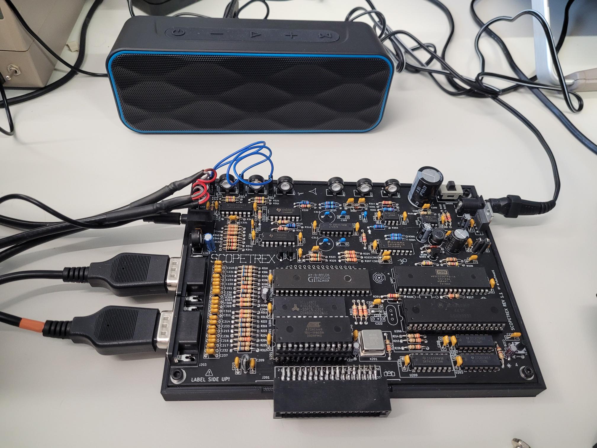
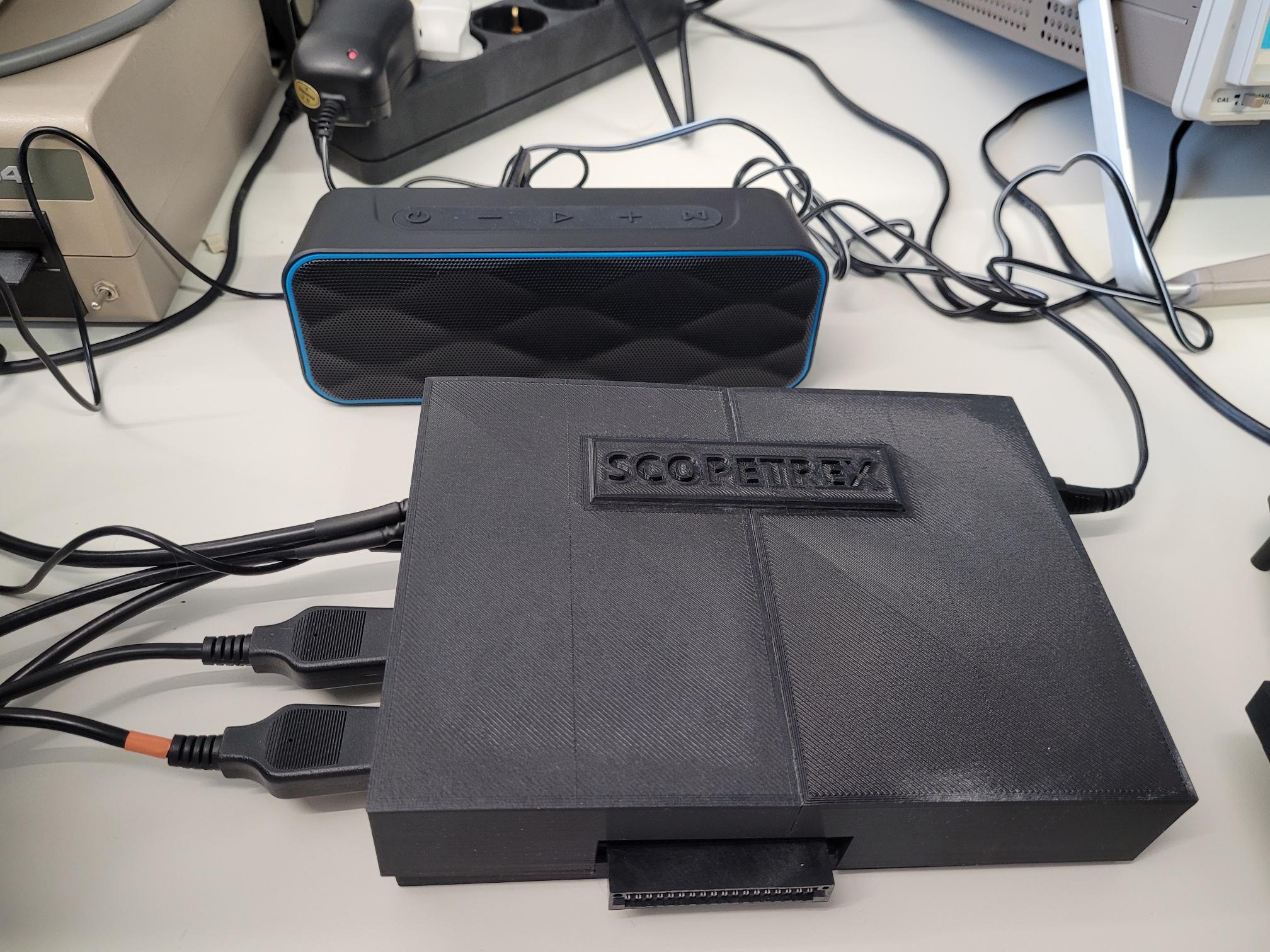
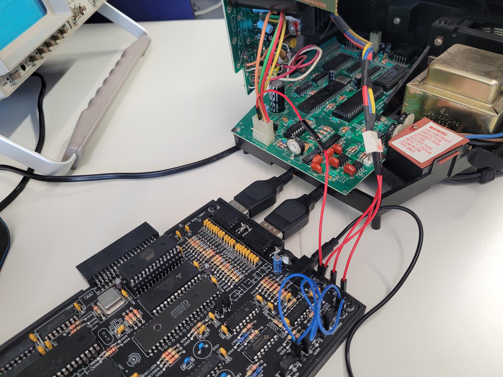
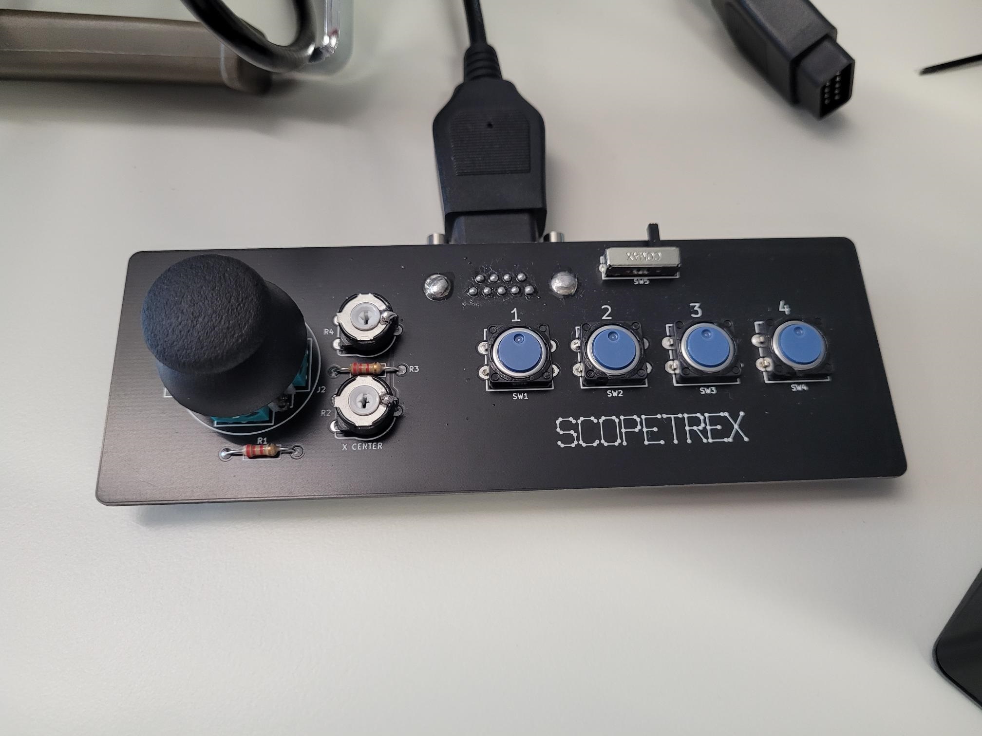
- Experiments with a SCOPETREX board (for
information about SCOPETREX, see here)
- The board used here was assembled by one of my
students as a tutored project work.
Project
Status
- Ongoing, just started
- Assembly of the board is completed, first
tests were successful (see pictures below).
- To be continued...
Picture
Gallery
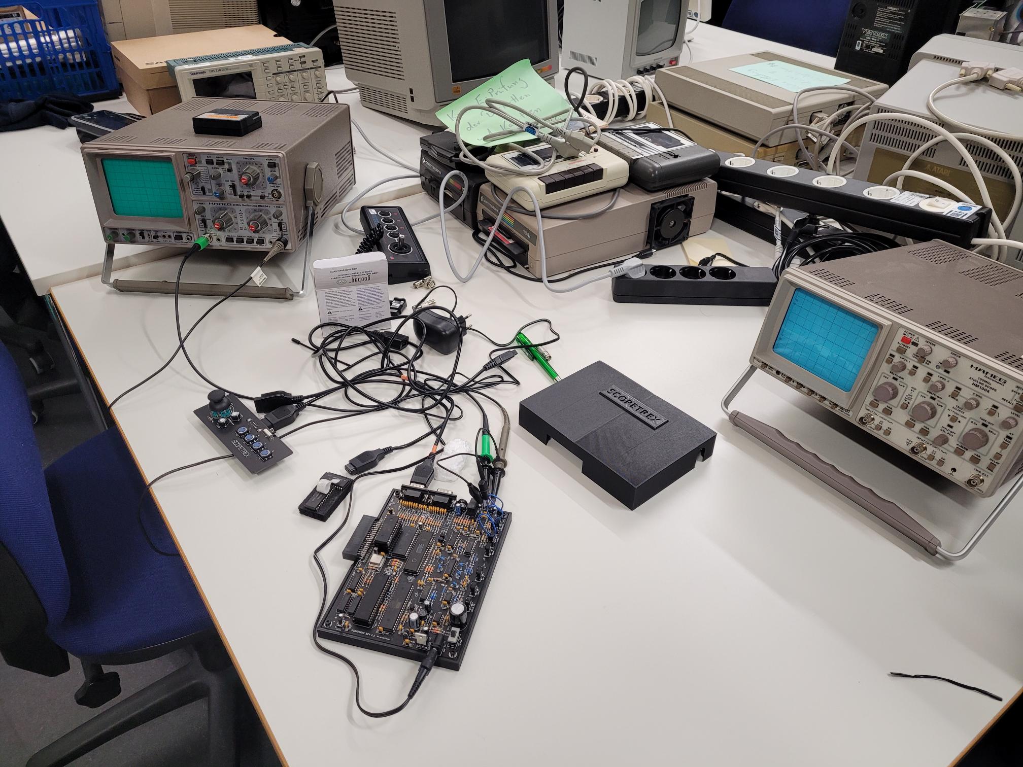  
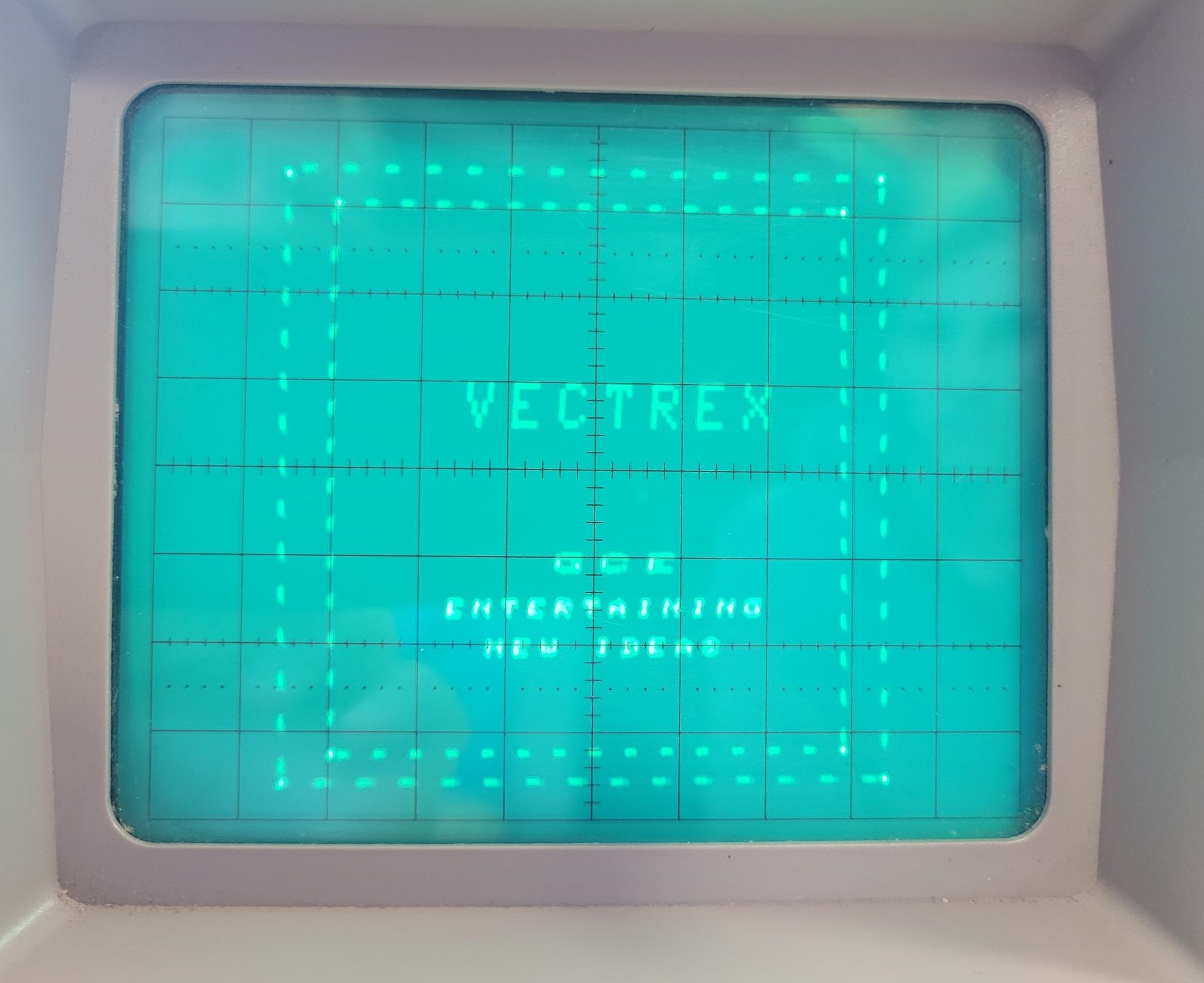
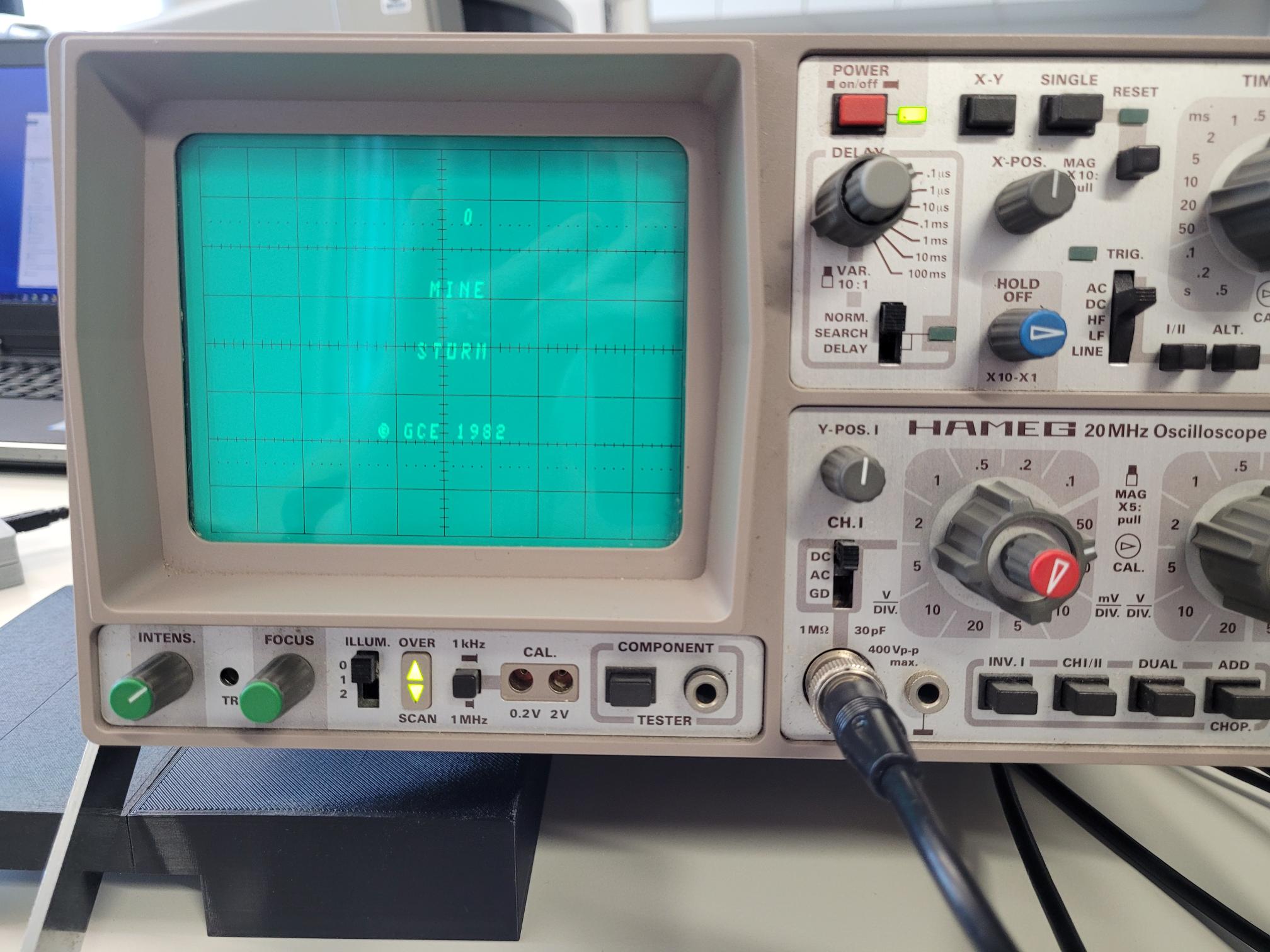
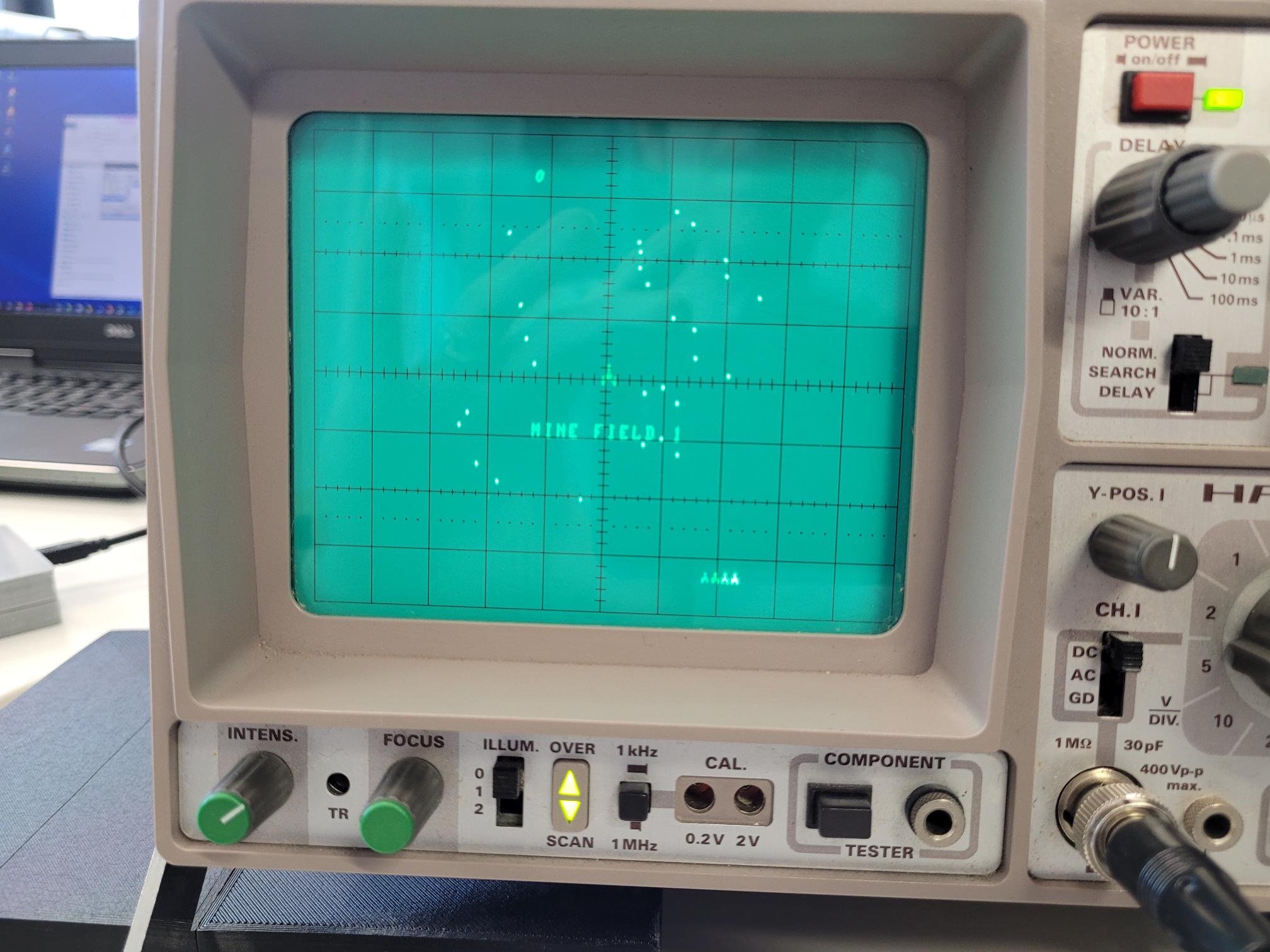
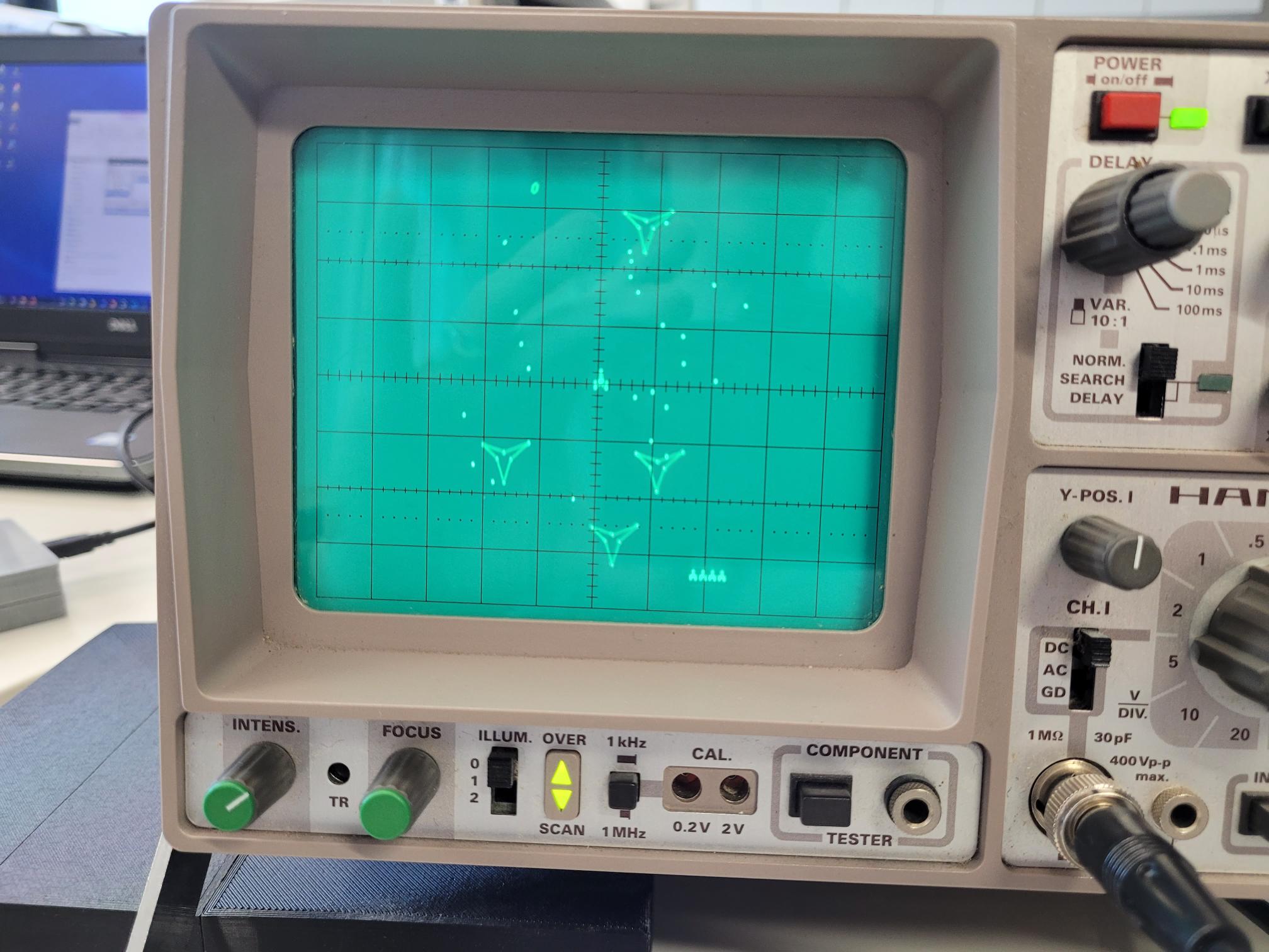
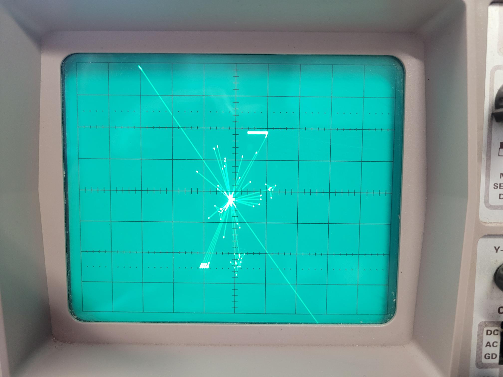
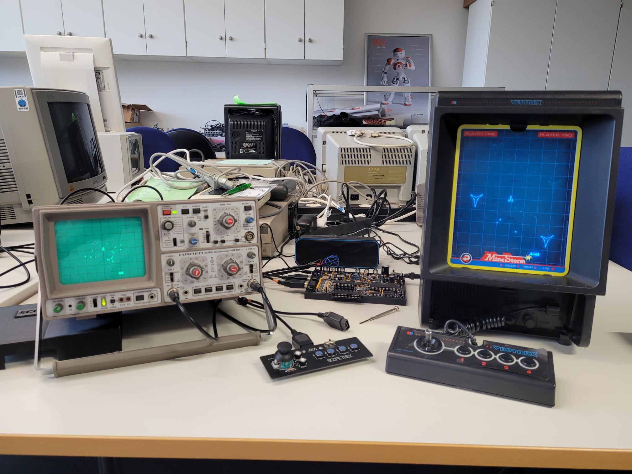
The SCOPETREX board on my
oscilloscope
- The oscilloscope is a HAMEG 204 in YX
mode, using the additional Z-input to
control the blanking of the electron
beam.
- The quality of the pictures is
sometimes a bit poor, but just because
of the camera used to take the picutres.
On the oscilloscope, the display is
amazingly great.
 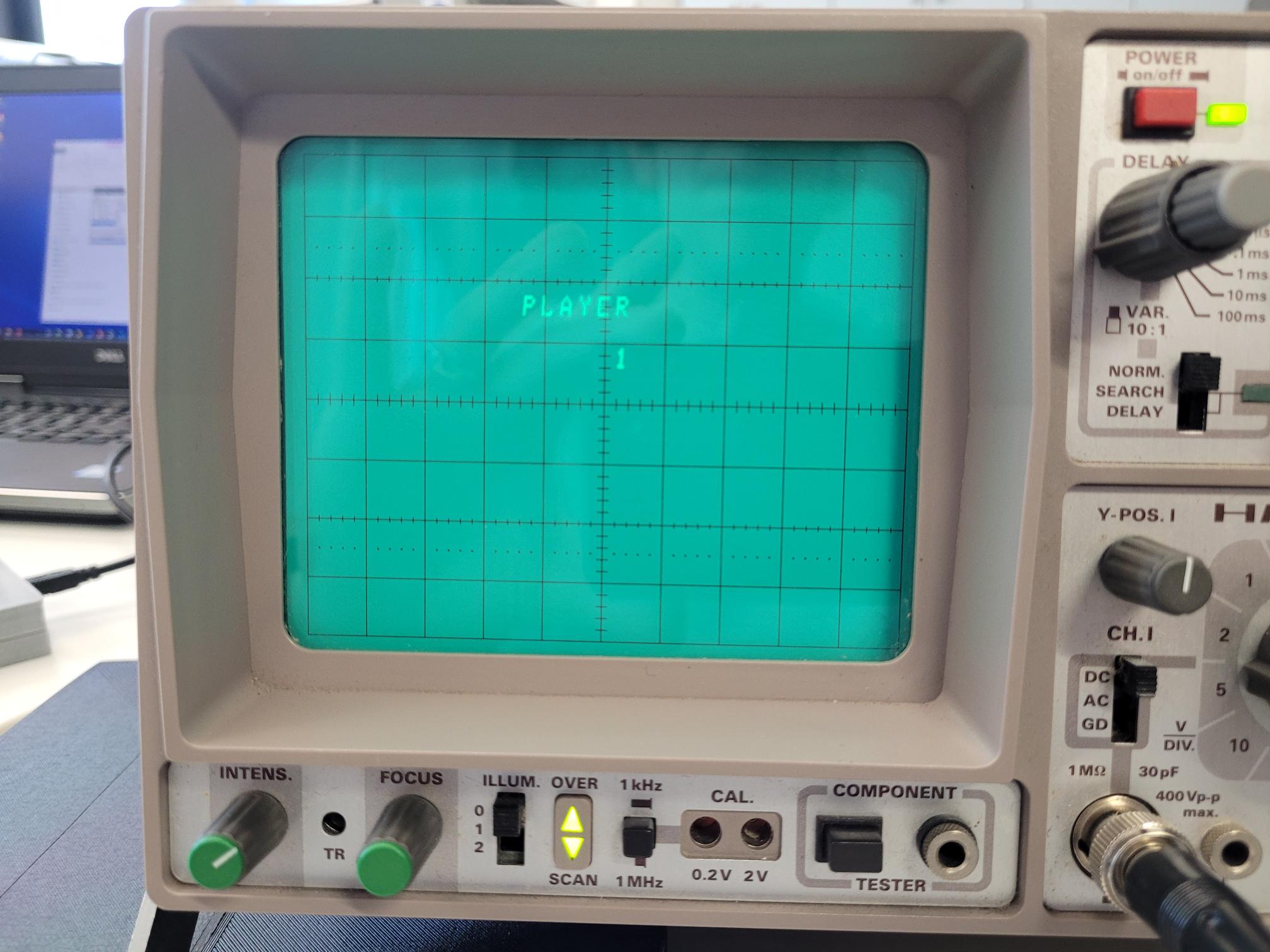 
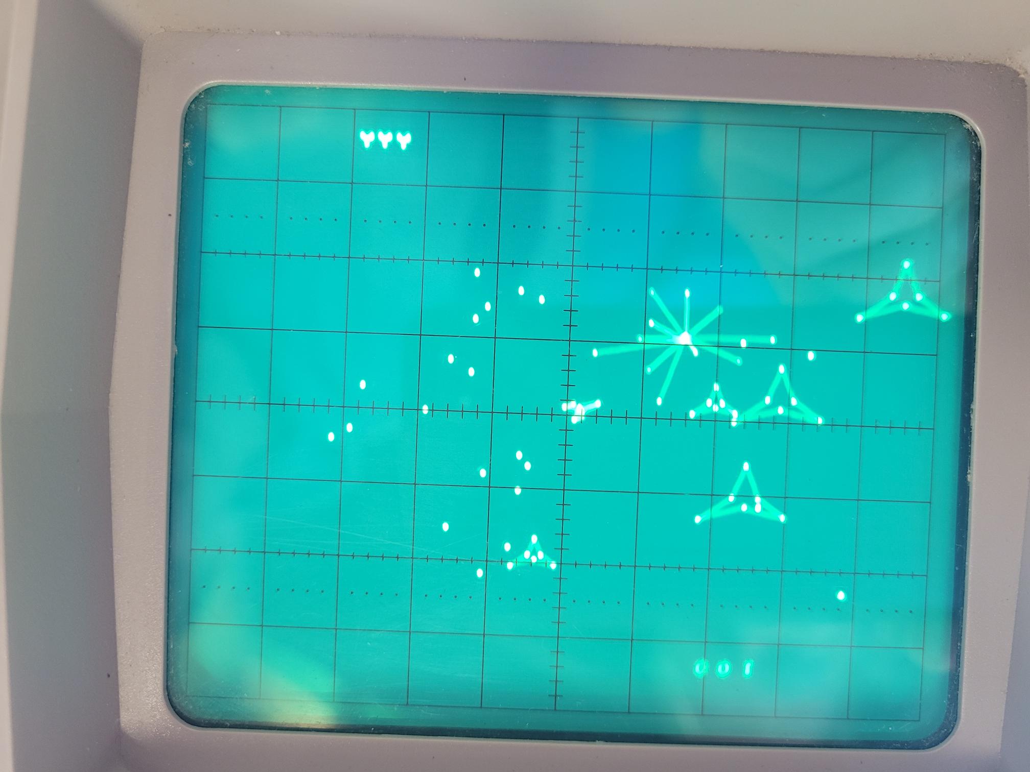 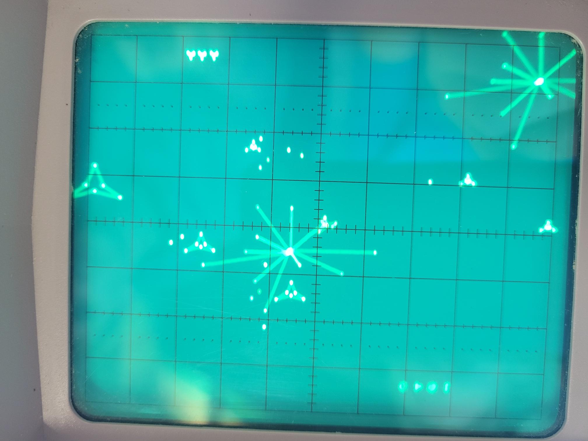 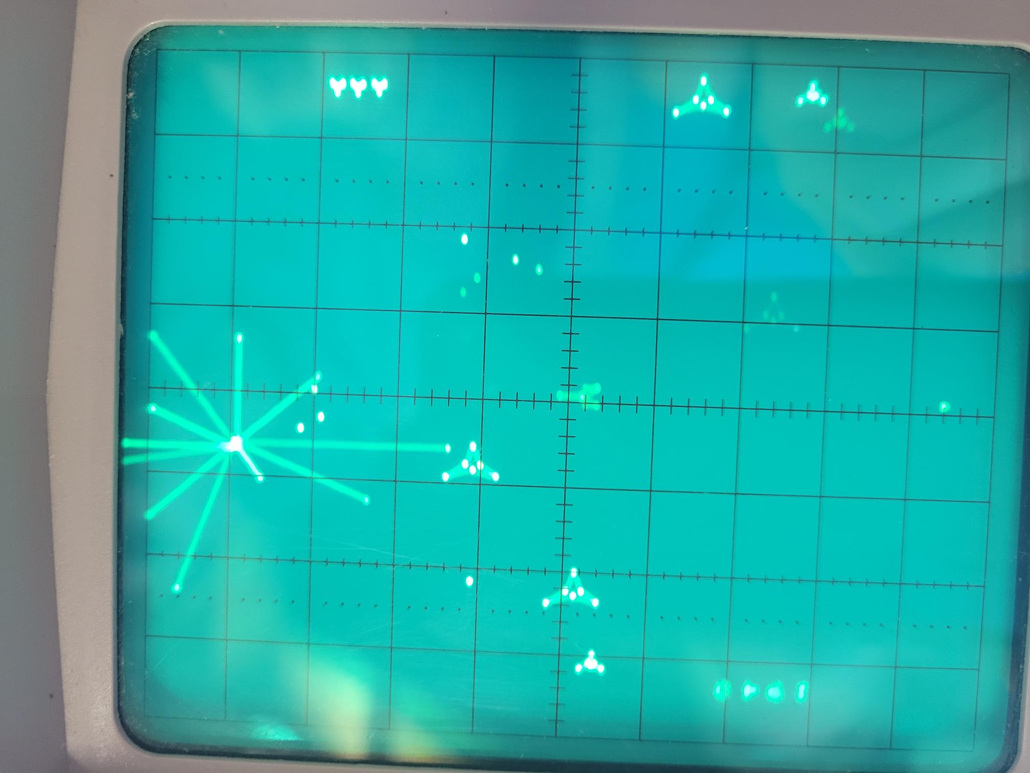
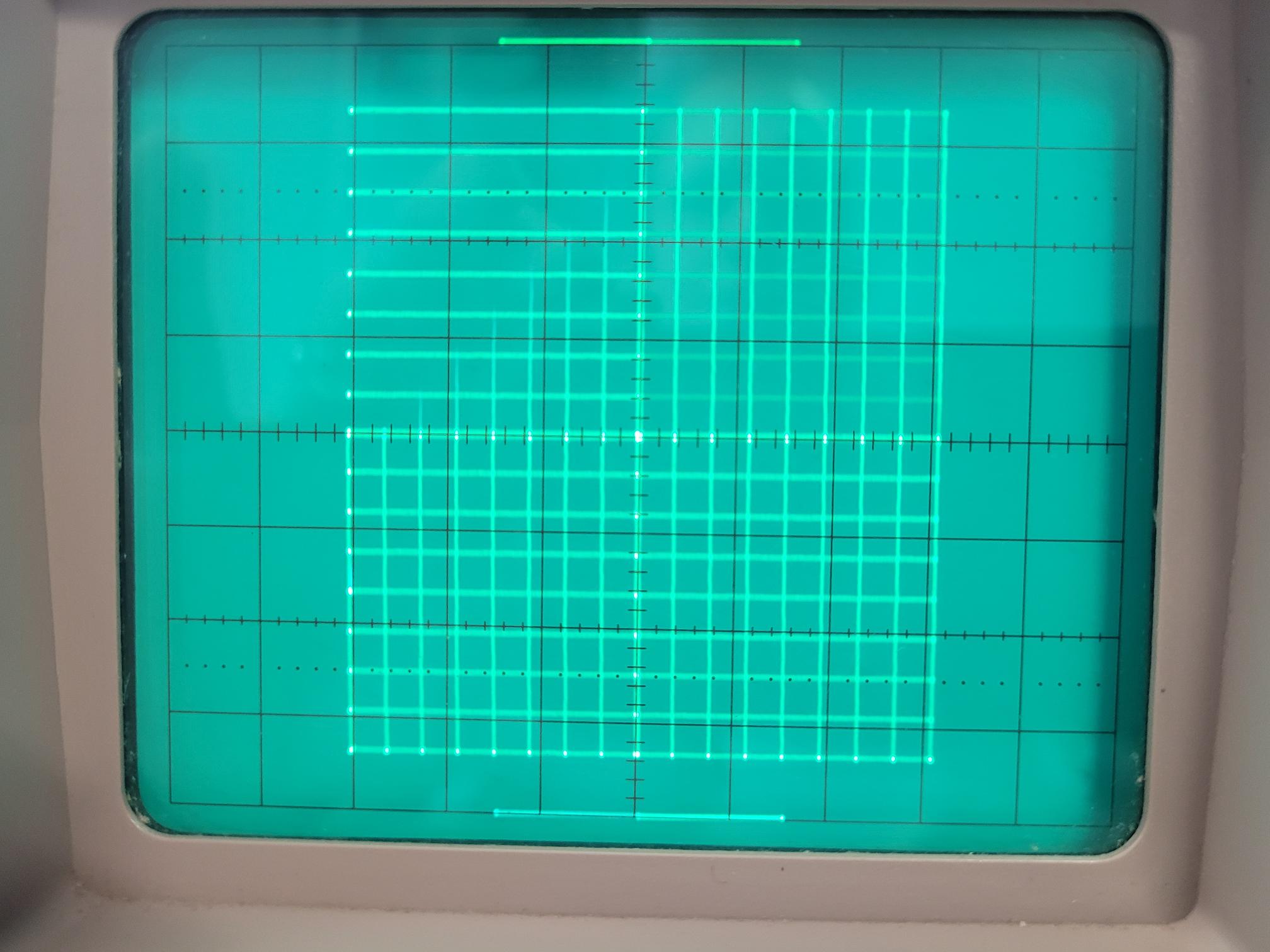
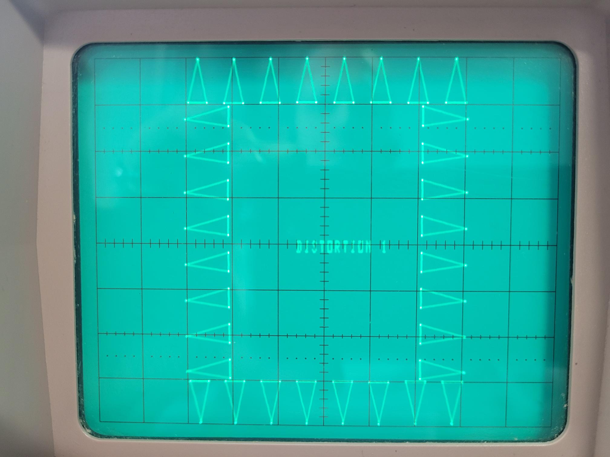
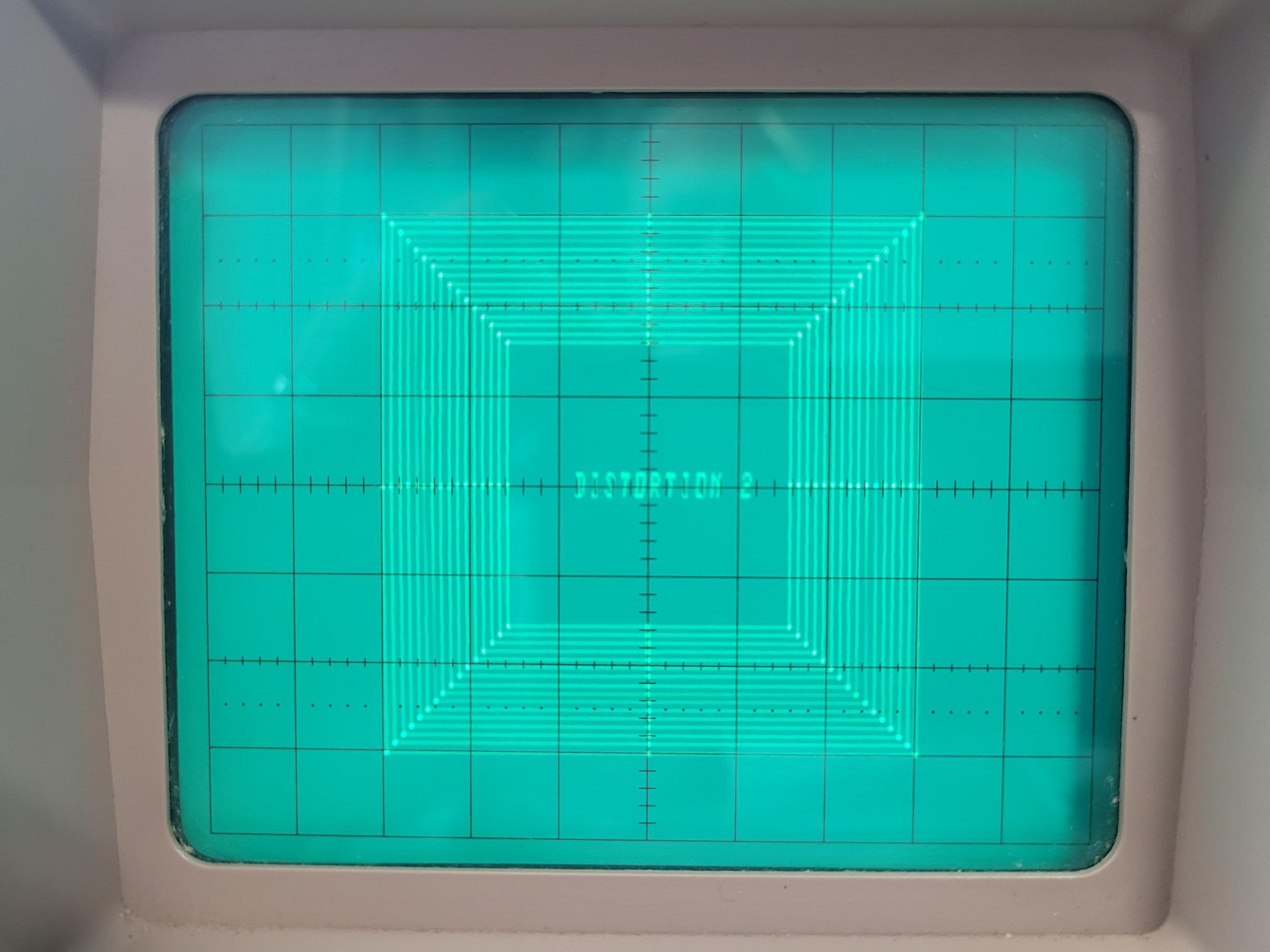
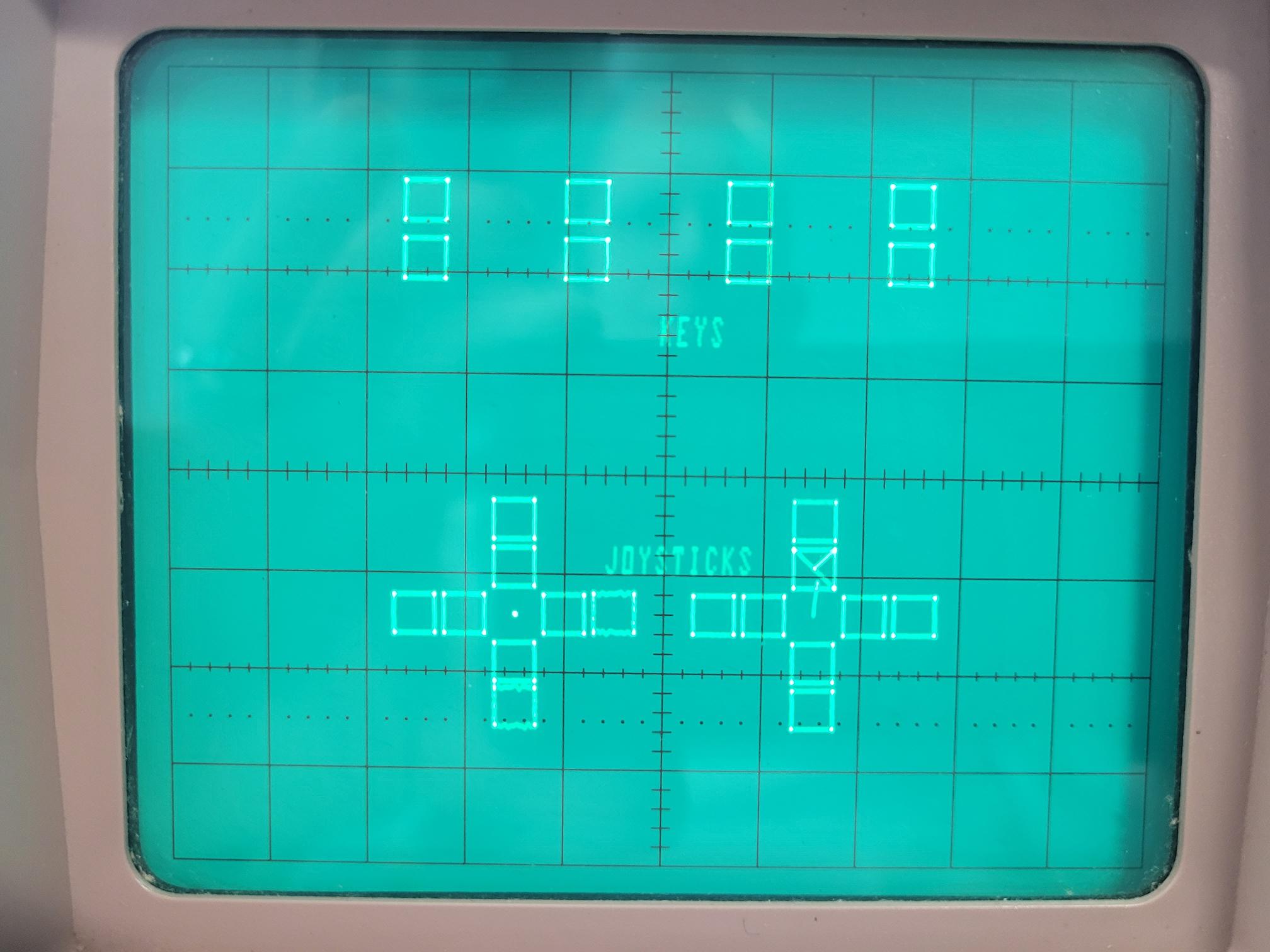
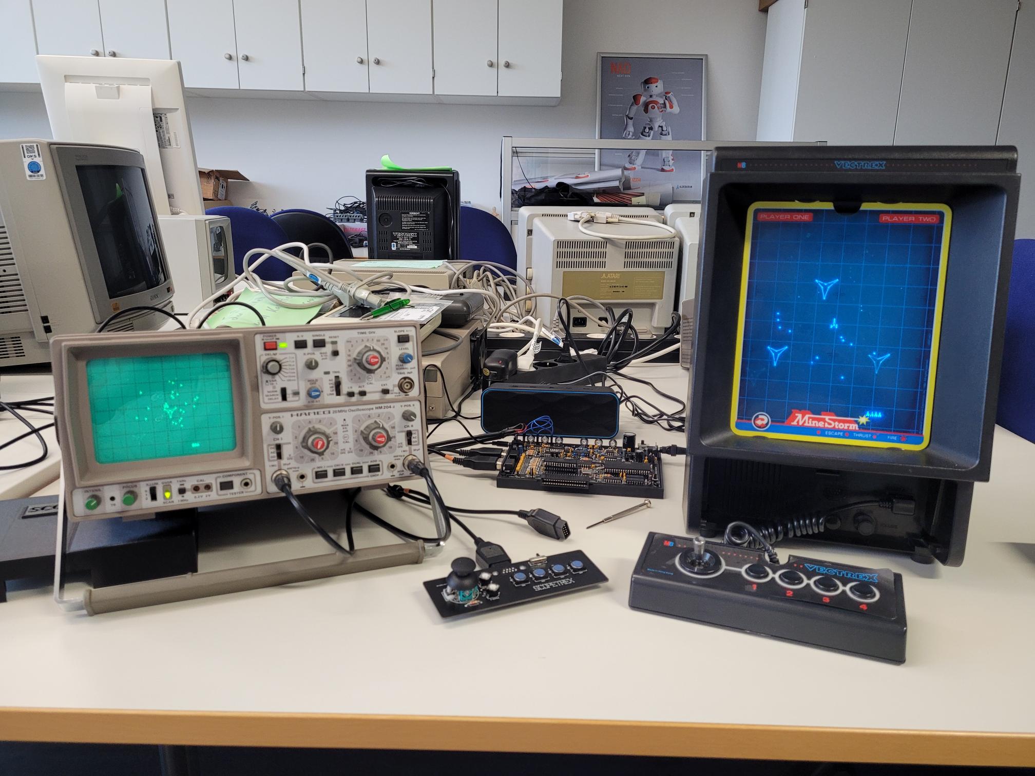
Using the Test Rev4
cartridge to calibrate the
board
- It is sort of eerie how
perfect the Test Rev4
cartridge works for
calibrating the output of
the SCOPETREX board on the
oscilloscope. Note the
alignment of the vectors
to the raster lines on the
oscilloscope screen.
 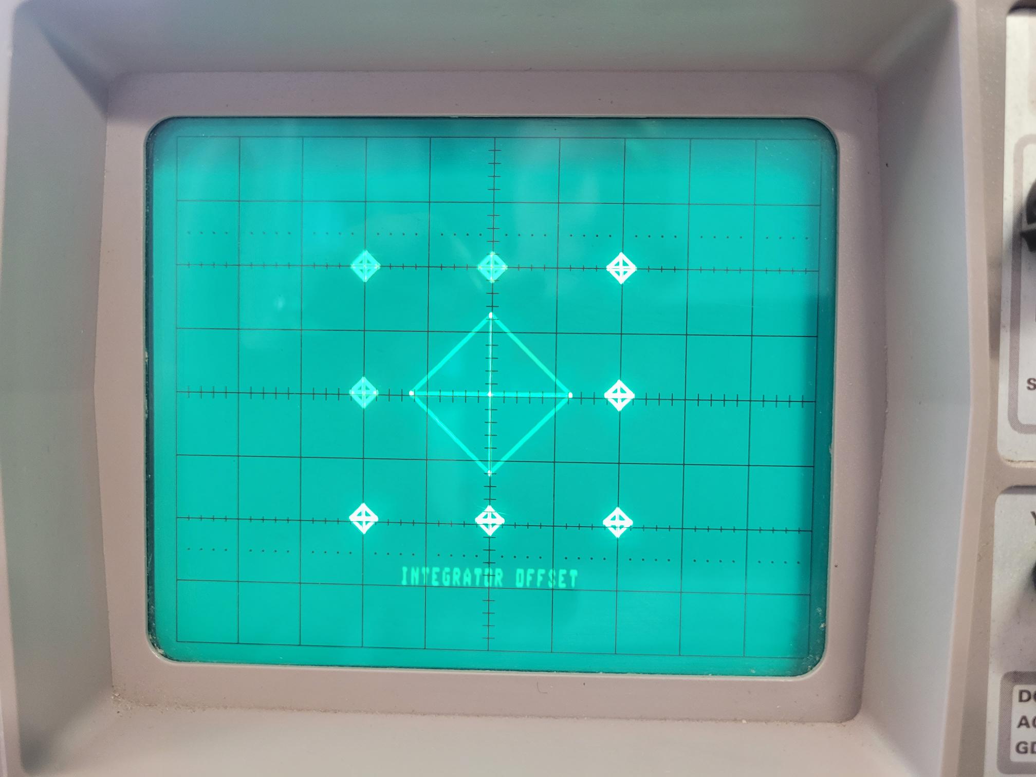 
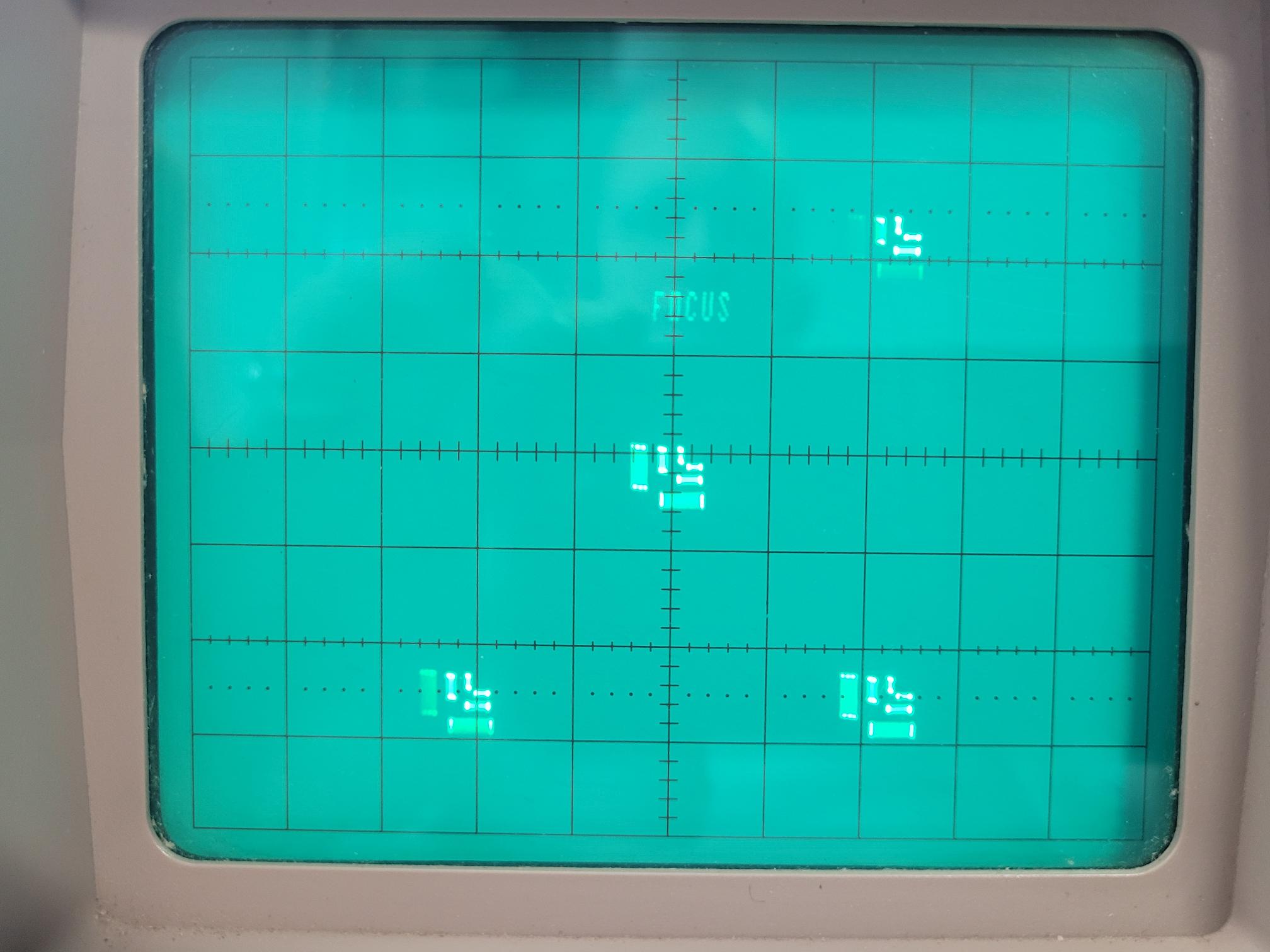  
- The "Focus" test of the
Test Rev4 cartridge is
good and useful for
calibrating the "Focus"
setting of the
oscilloscope. I do not
know of any focus
adjustment in the Vectrex
hardware, so maybe this
test was originally
programmed and used with
an oscilloscope and/or the
tube protypes while the
actual Vectrex hardware
was still being developed?
- My speculation is that
the Test Rev4 cartridge
was there first. Before
the Vectrex BIOS was
completed. This
speculation is derived
from the fact that the
Test Rev4 code contains
and uses several copies of
BIOS routines (see here),
so
some tests actually run
without using the BIOS.
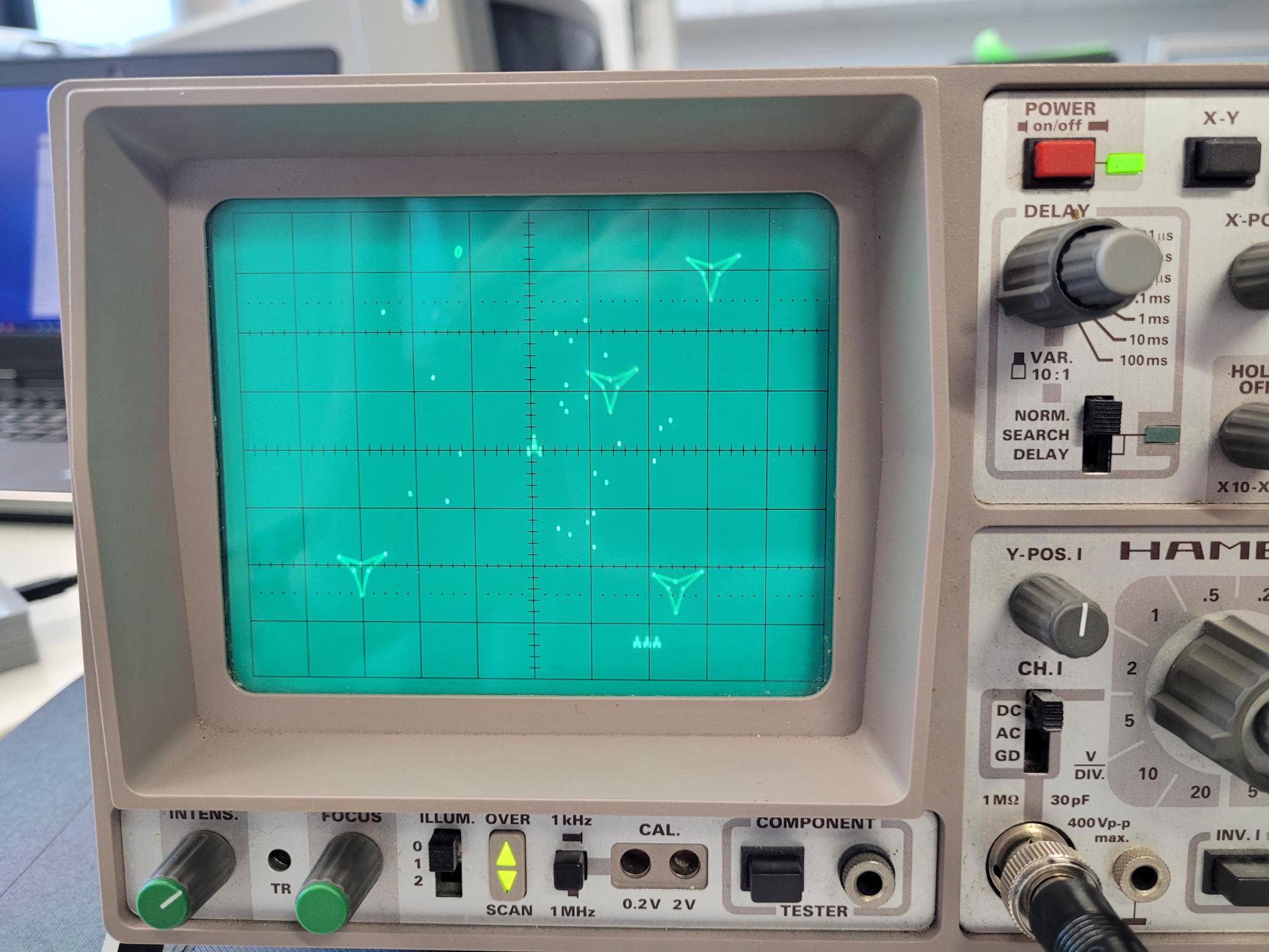
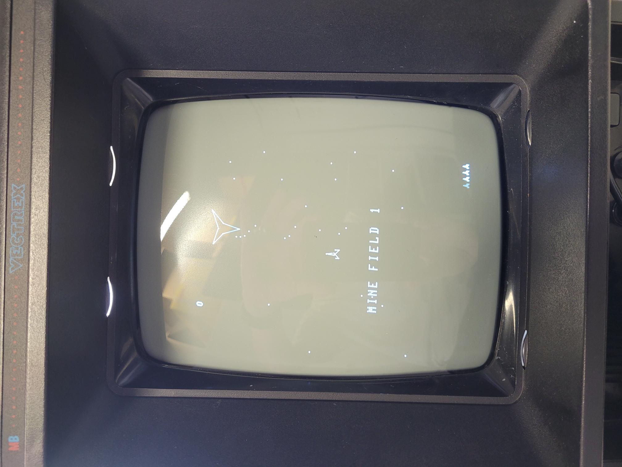
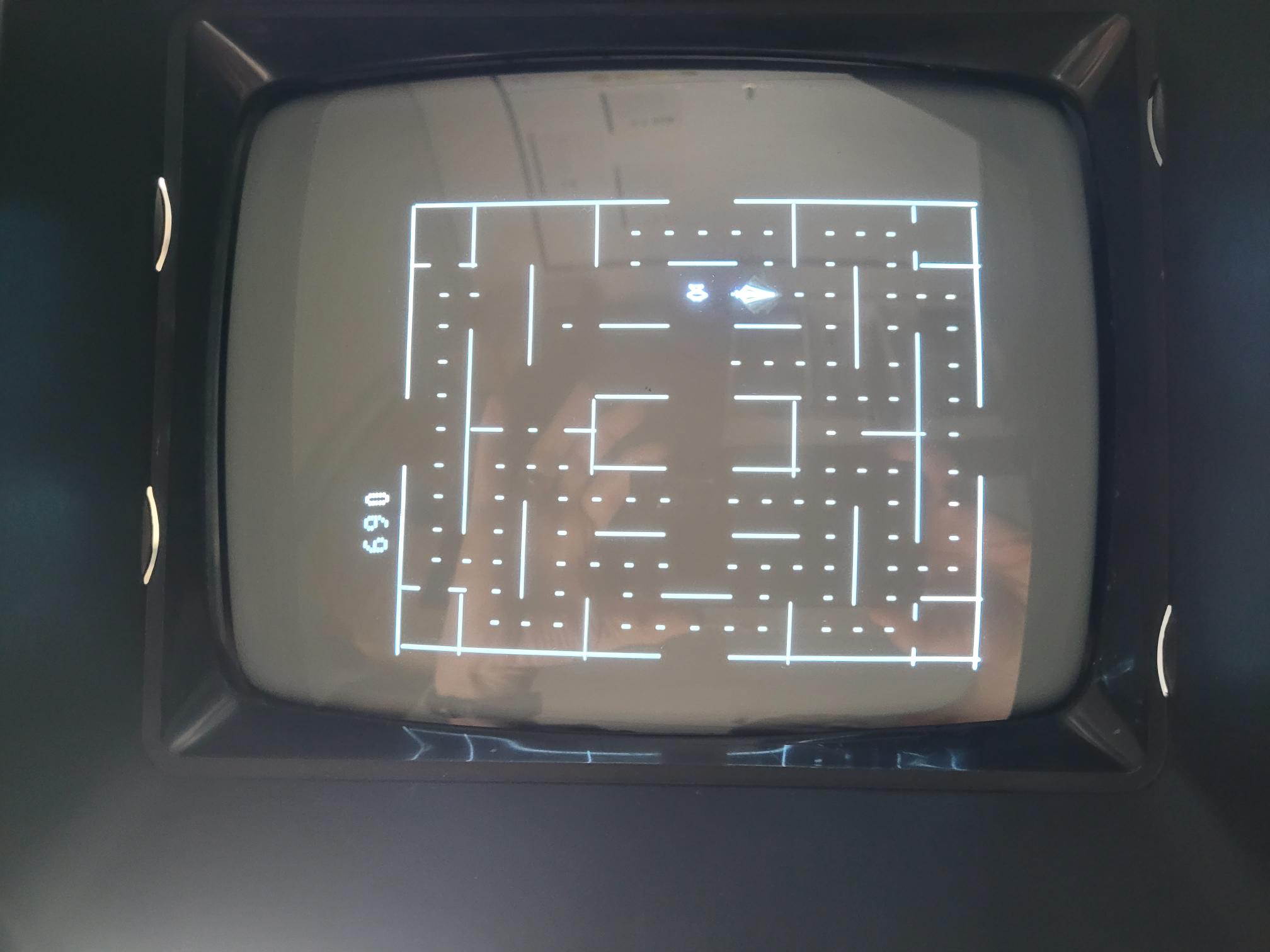
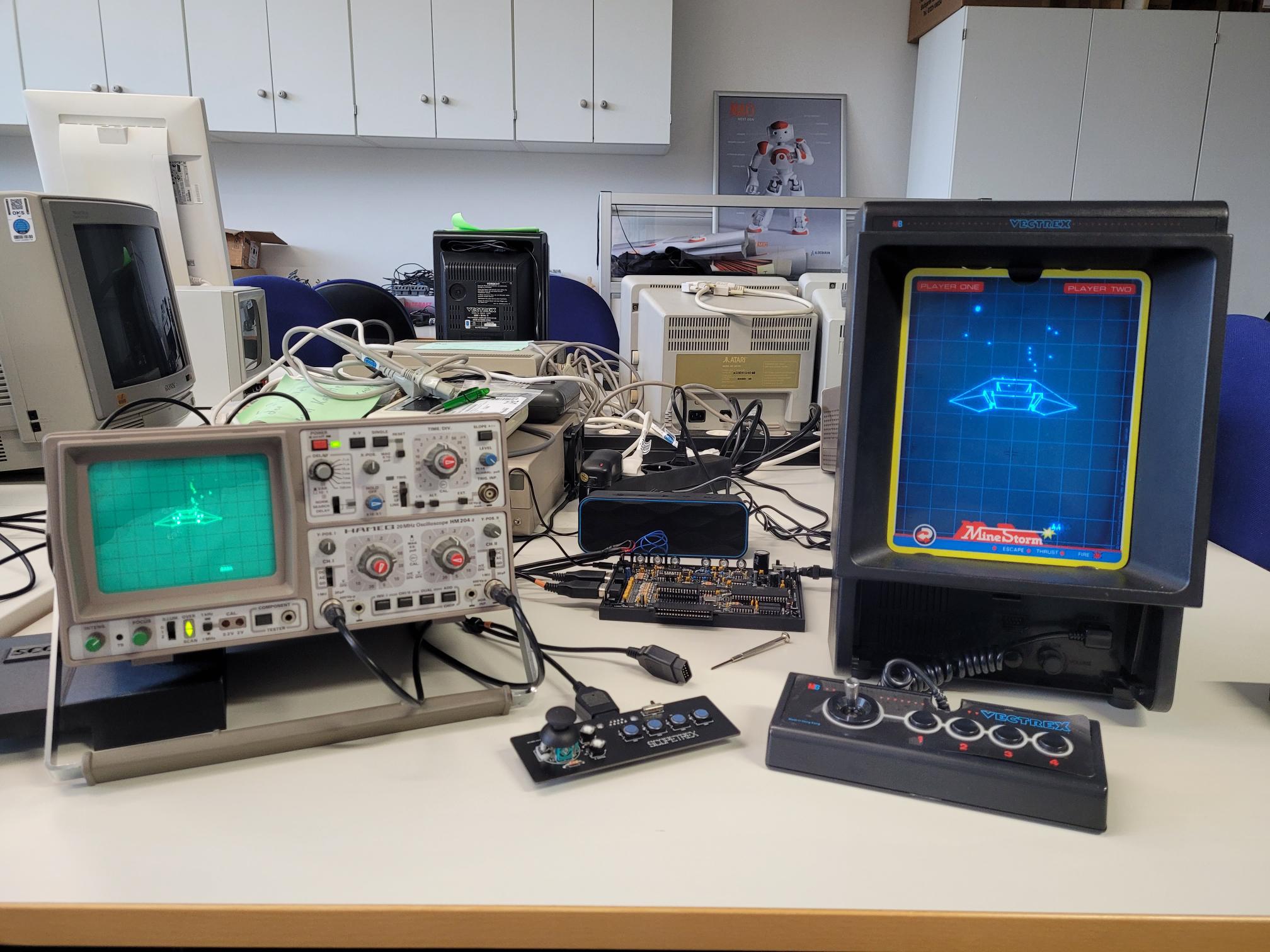
The
SCOPETREX
board
connected to a
Vectrex CRT
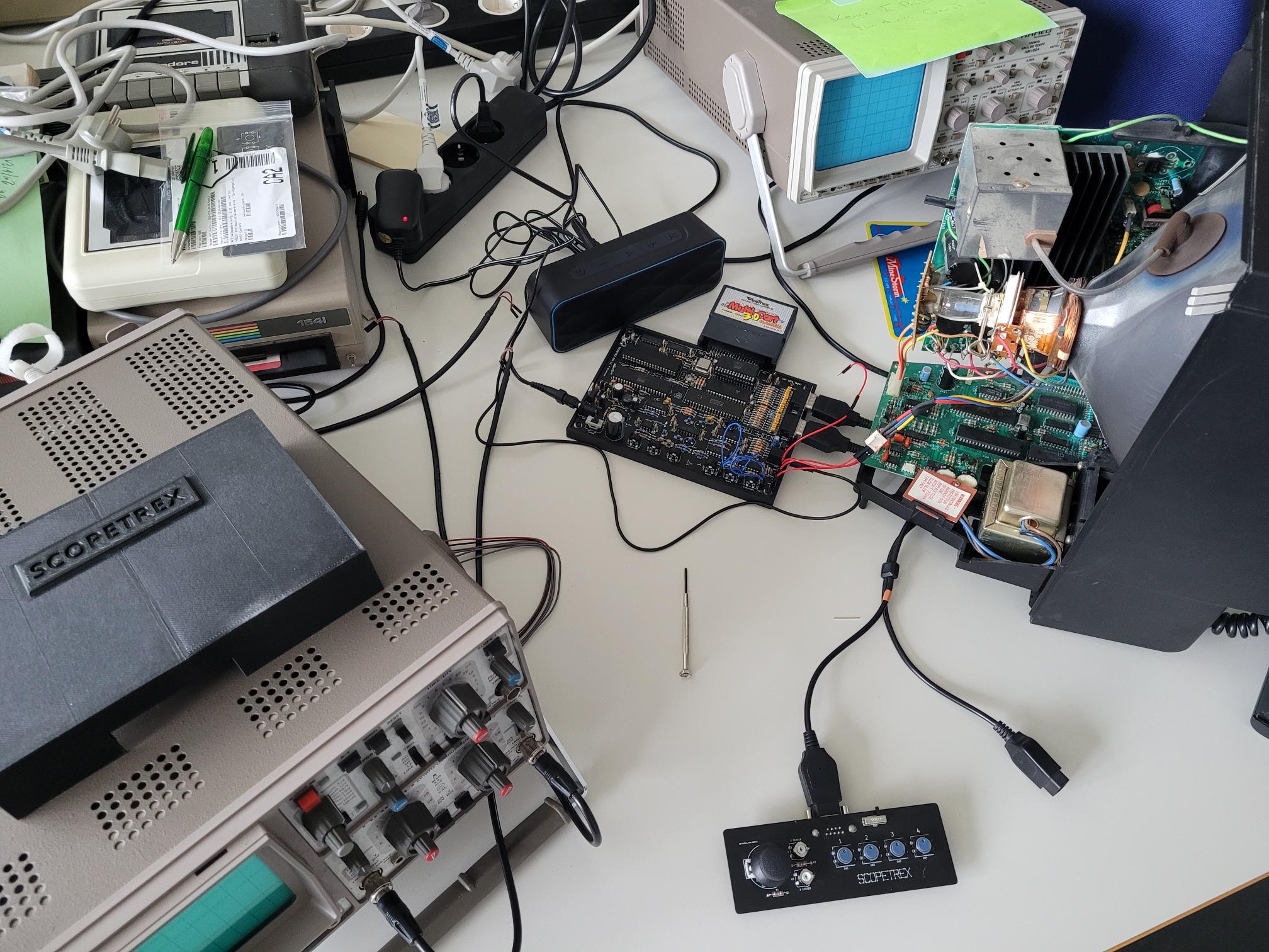
- As a
second
experiment, I
disconnected
the logic
board of my
Vectrex
console from
its analog
board, and
then connected
the SOPETREX
board to it.
Many thanks to
Brett
(playvectrex)
for his
long-distance
support and
helping me
getting
properly
grounded
signals here.
- I have not
found any
information on
the internet
about someone
having tried
this before,
so I am
posting some
pictures here.
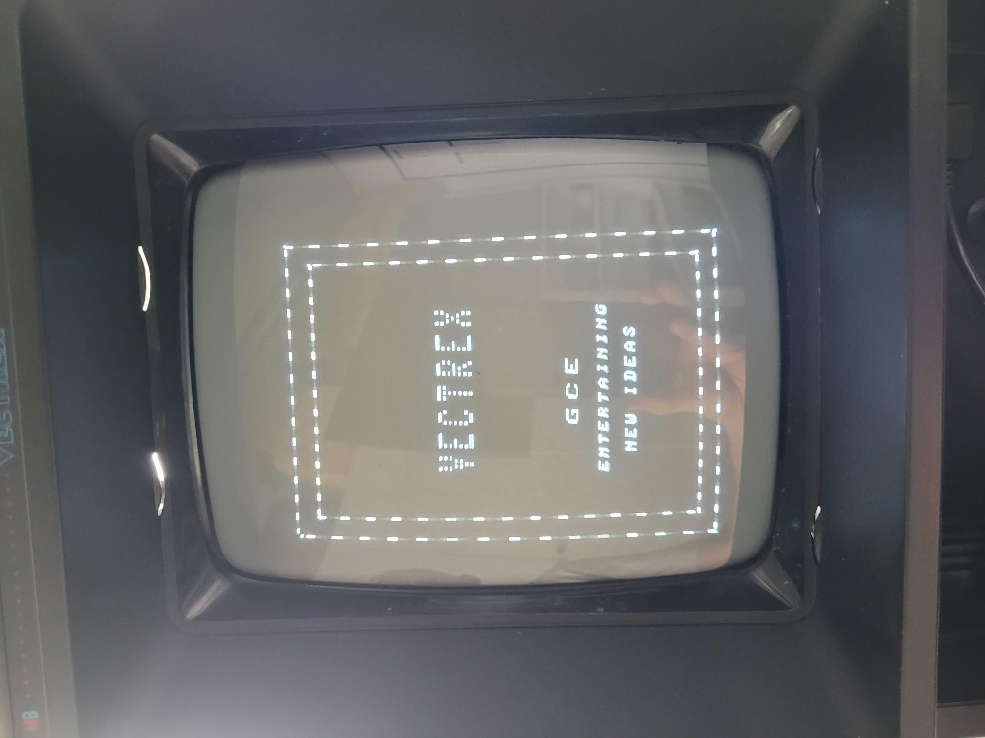 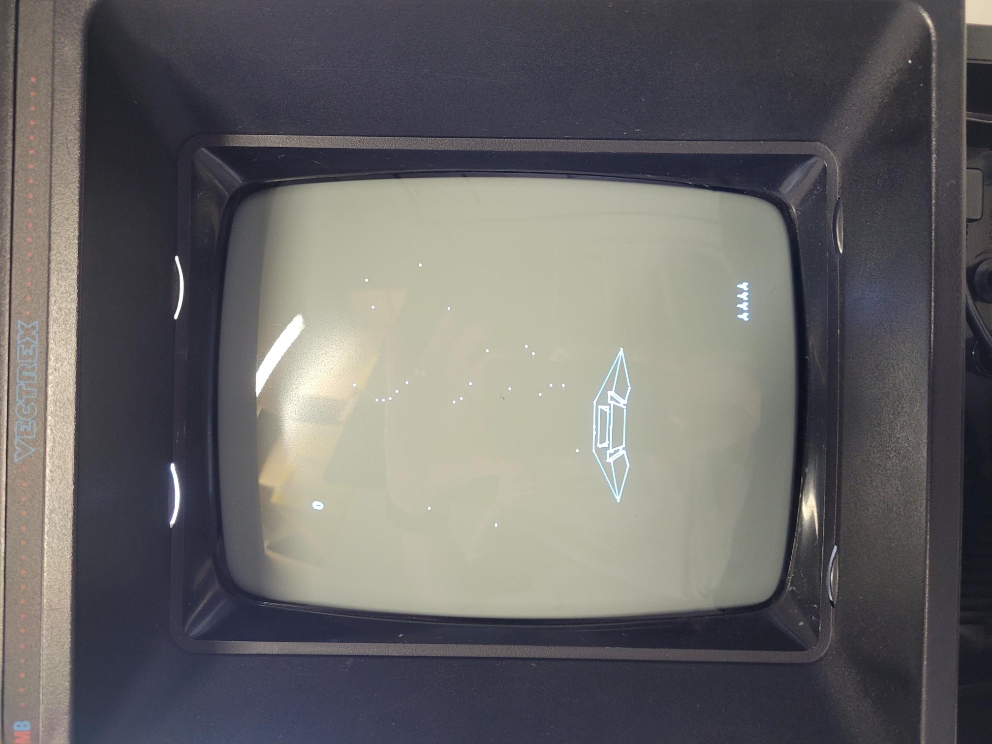  
- Note that
the display is
not perfectly
centered. That
would involve
realigning the
coils of the
Vectrex CRT,
and I did not
do that in
order to be
able to easily
return the
console to its
original
state.
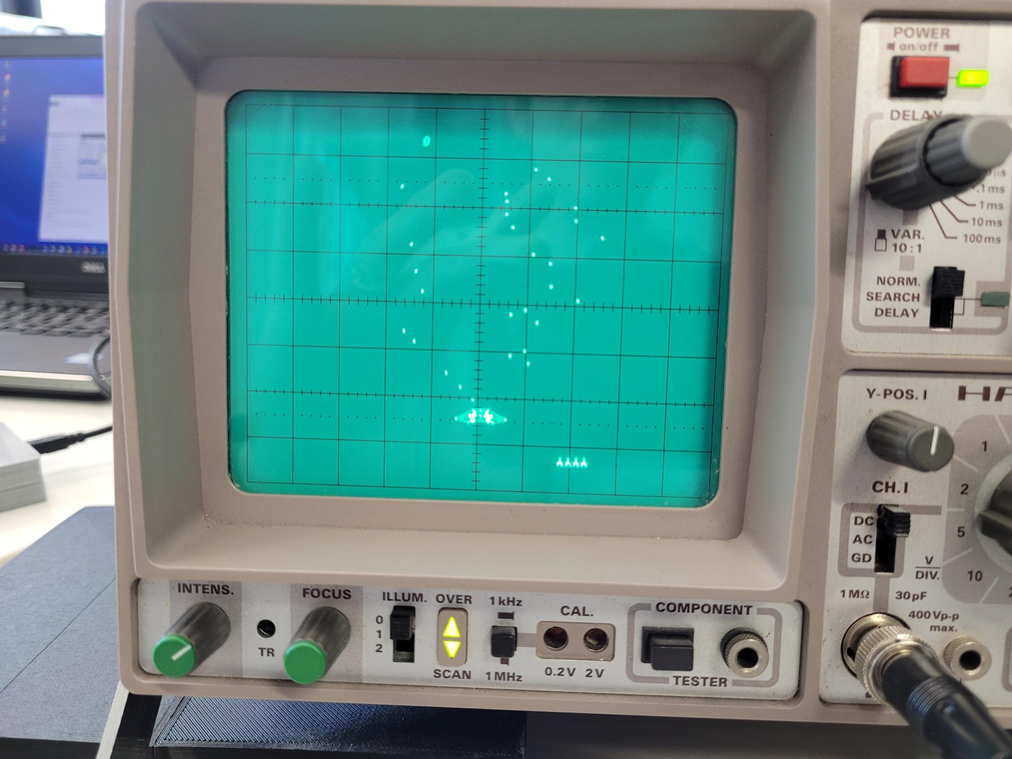
- Other than
that, I could
not see any
noticeable
difference.
The "new"
hardware of
the board does
not seem to
improve the
image quality.
Also the
infamous
mystery gaps and the slanted texts
are still
there, but we
already knew
that those are
inherent to
the DACs and
not a result
of aging. I
have not yet
tested how
vector drift
is with the
new board.
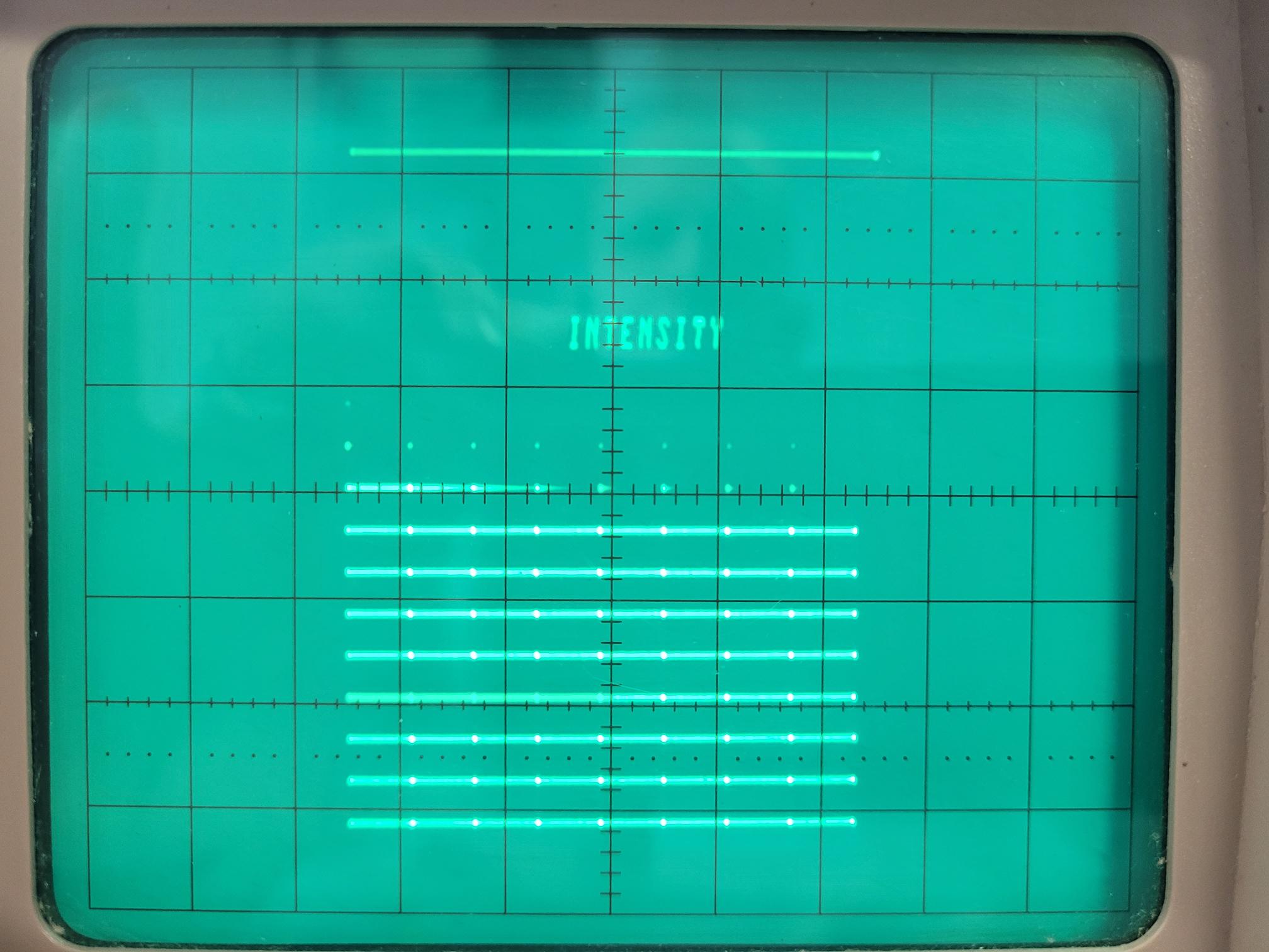
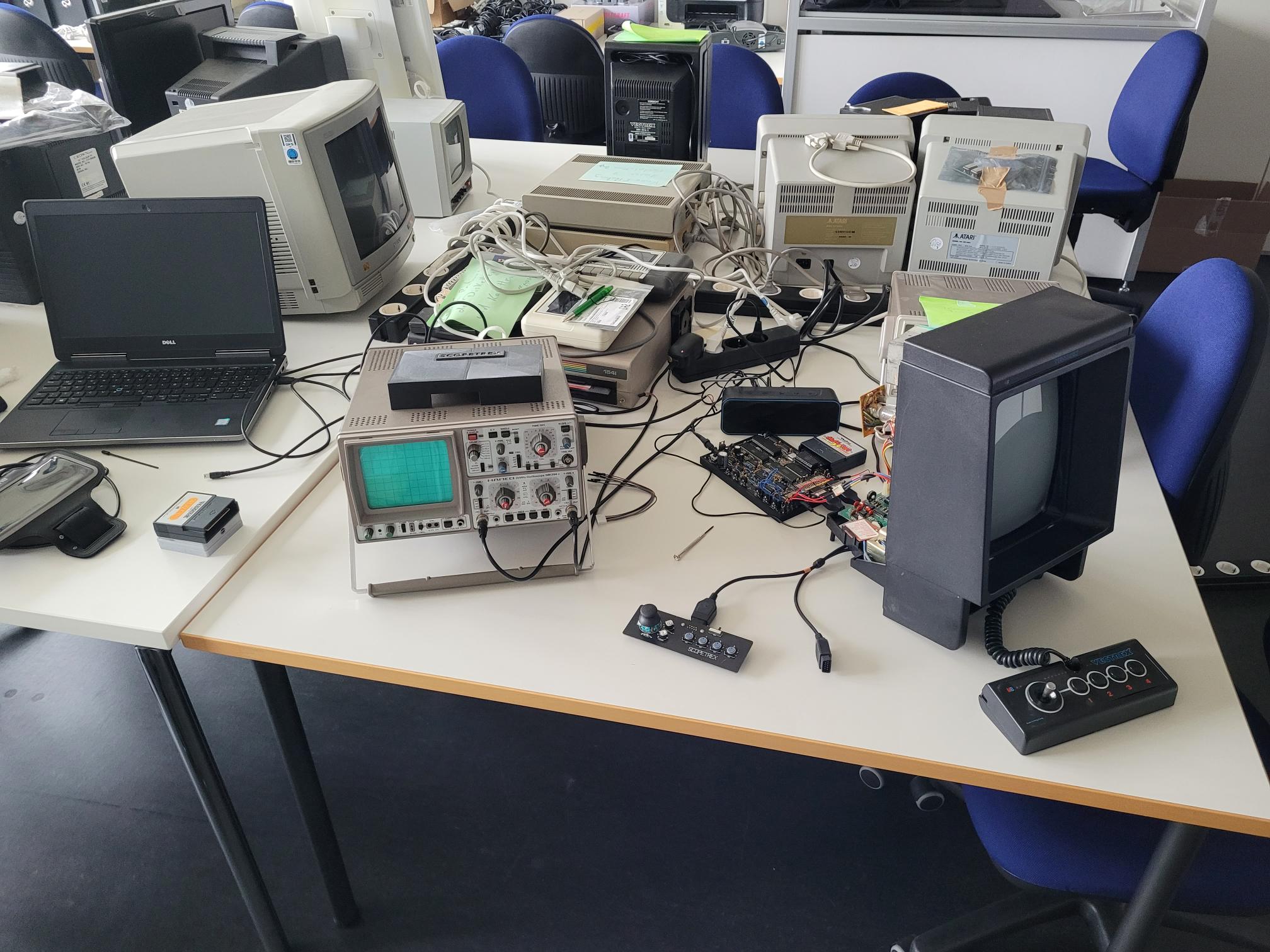
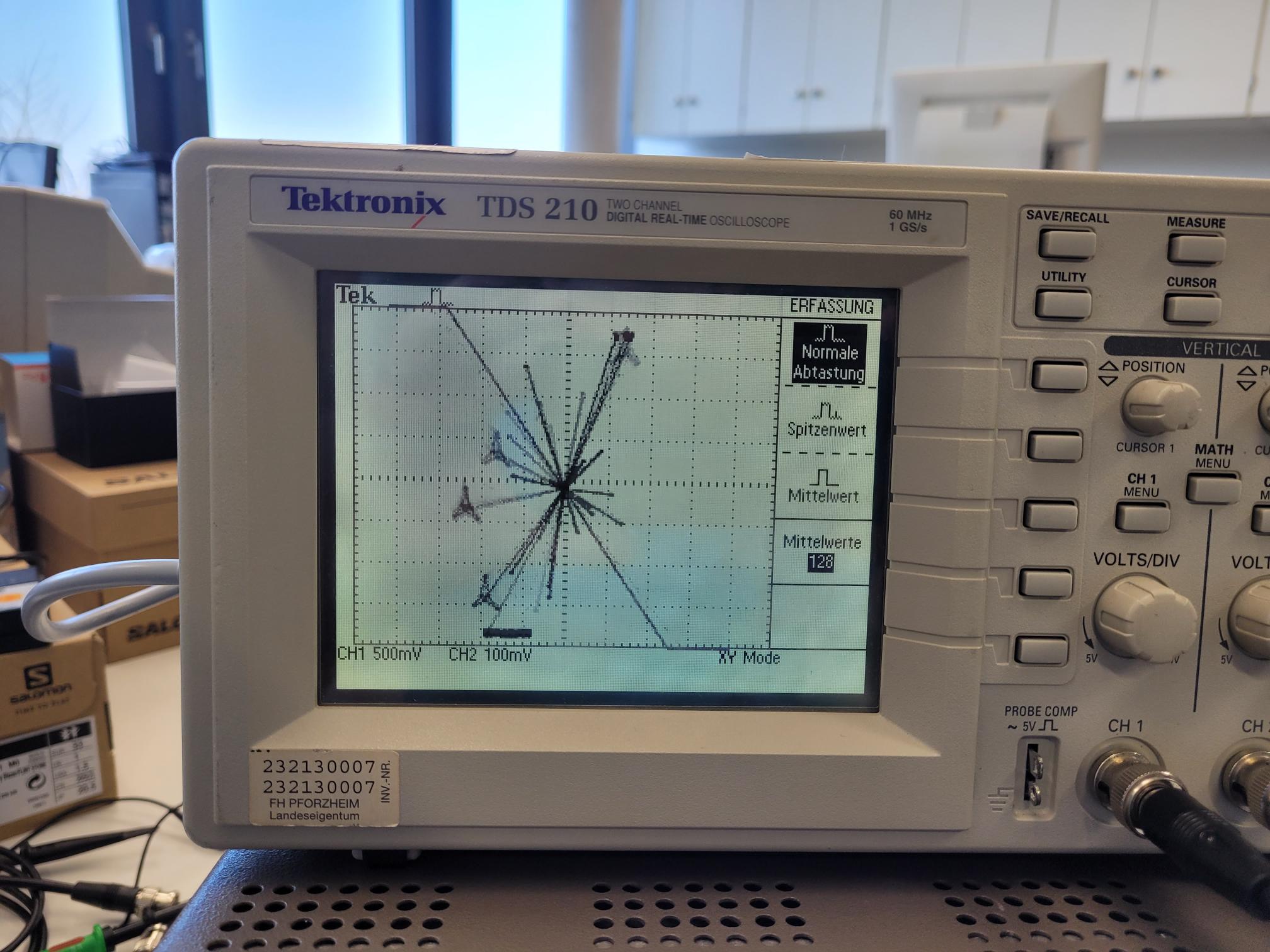
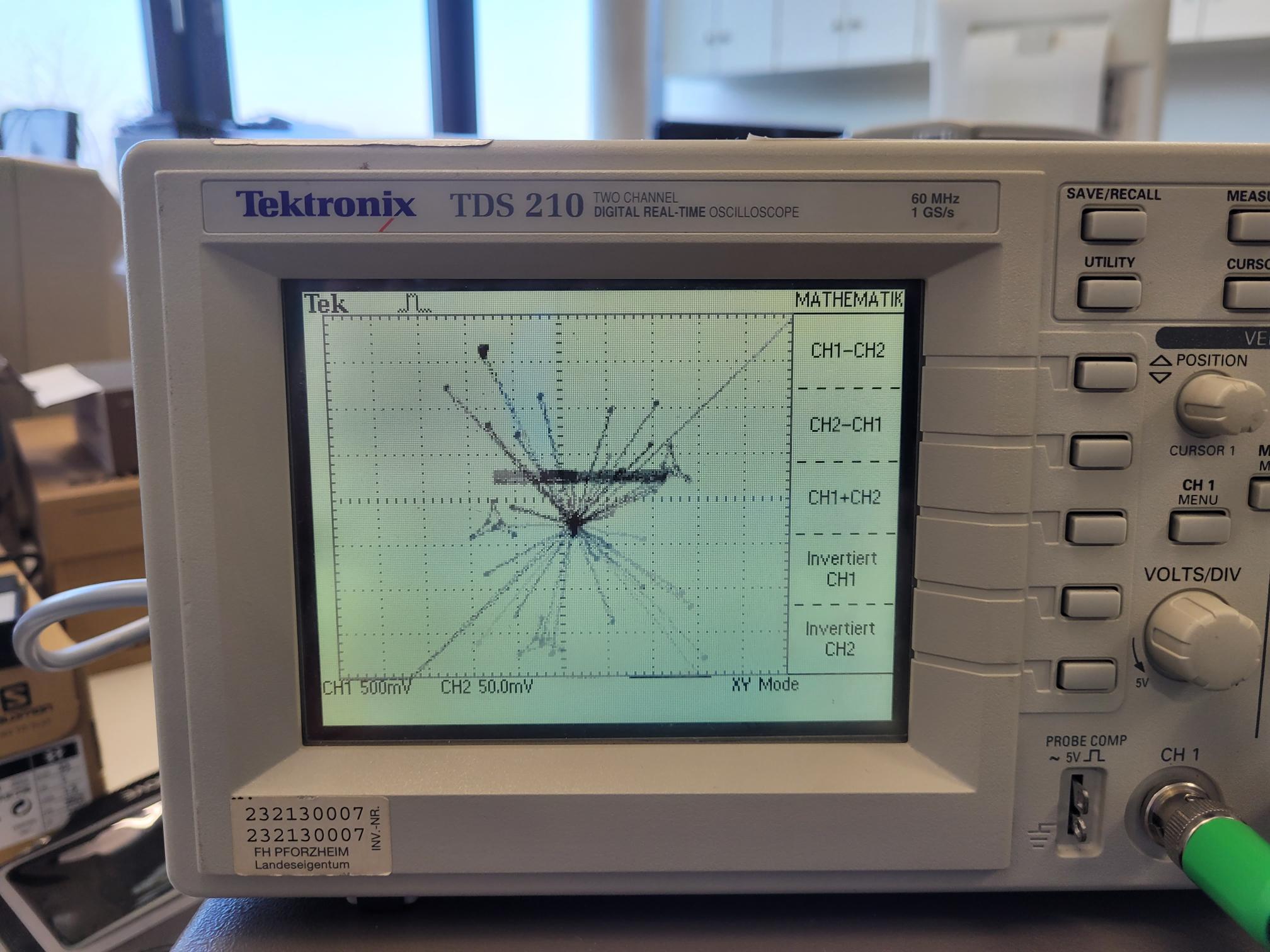
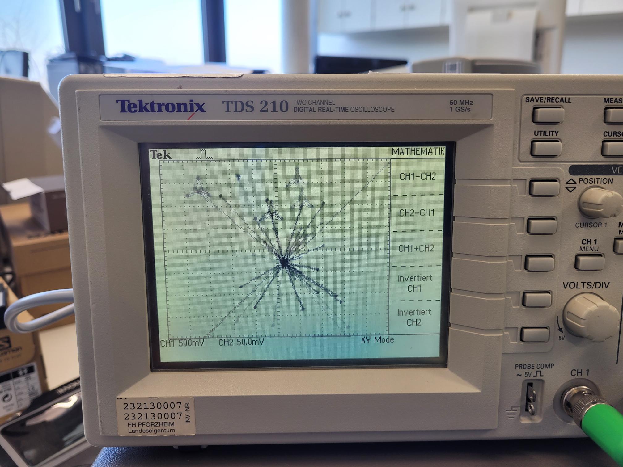
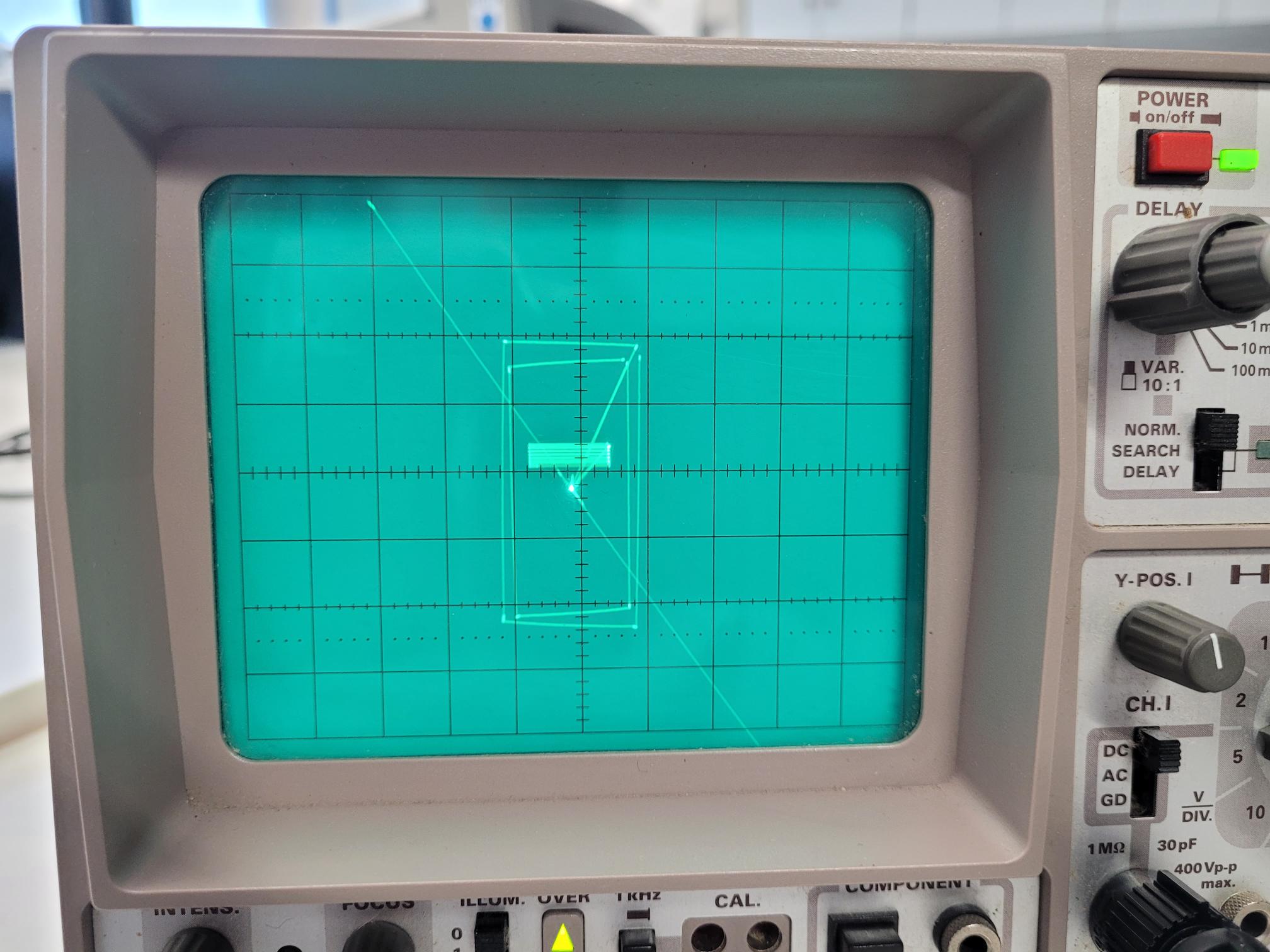
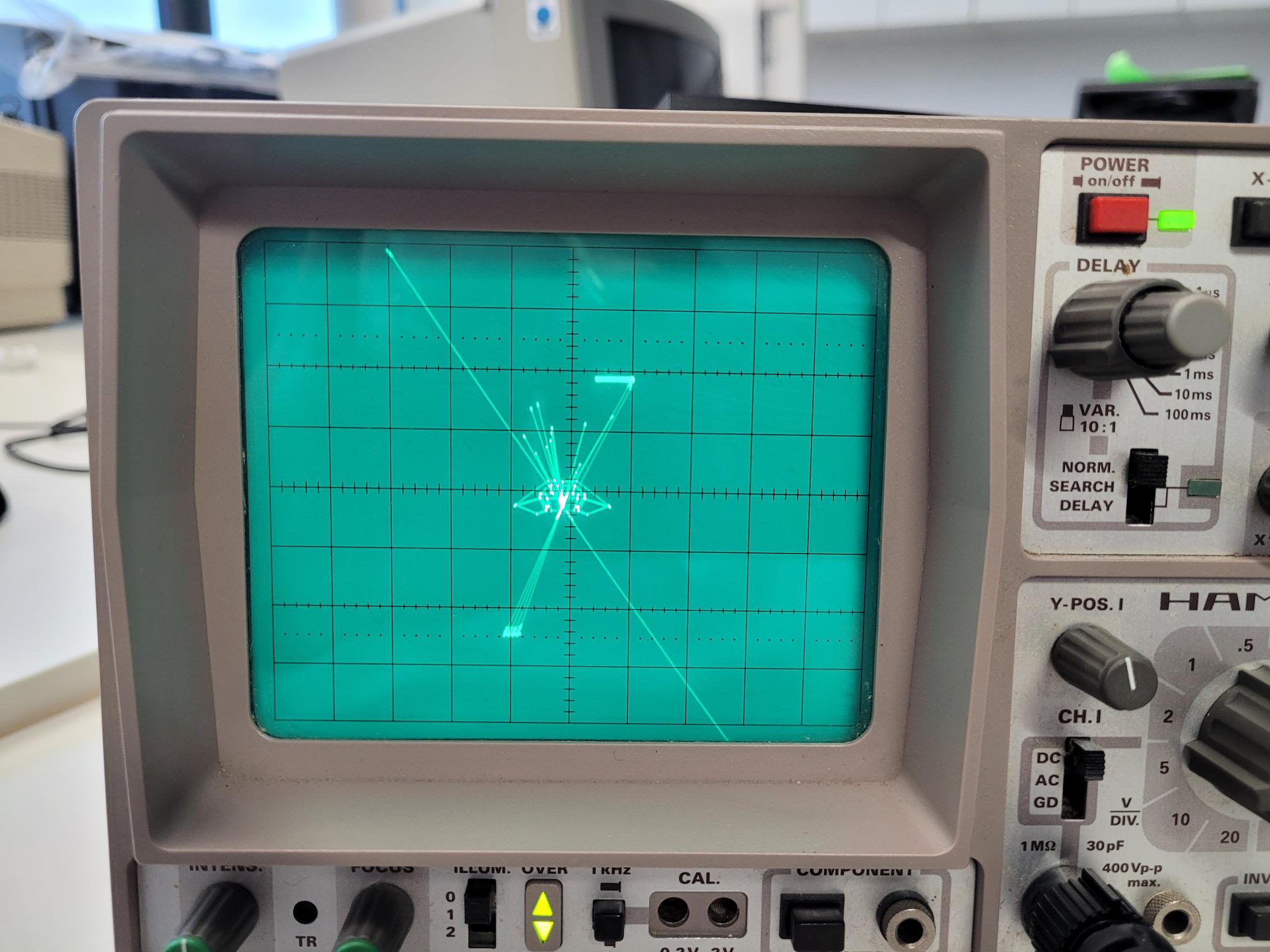
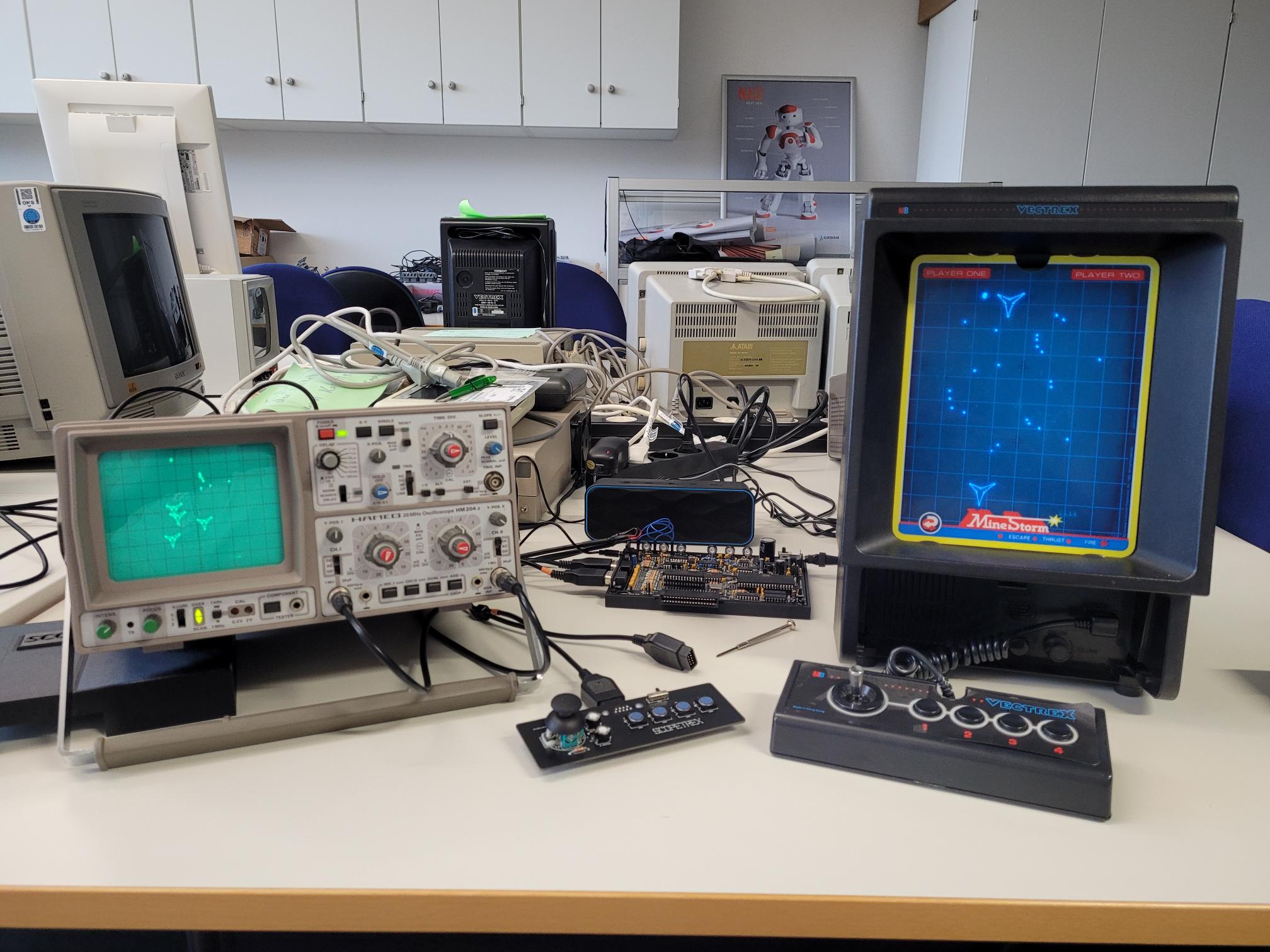
A
Vectrex console
connected to an
oscilloscope
- For the
sake of
completeness,
here are also some
picture of a
regular
Vectrex
console
connected to
an
oscilloscope
(a digital one
as well as an analog one).
Note that the
intensity
signal of the
Vectrex
console is not
correctly
handled by the
oscilloscopes
due to
internal
reasons, so
all lines are
visible. Still
an interesting
and valuable
method to
debug a
Vectrex
console.
Author
Latest
modification
on 01/17/2024, 11:30
|
